Just a short description and some simple test methods below of how a fuel injected Honda Wave AFS110i II throttle body works.
Honda AFS110. II 2012 - 2016. Throttle body in photos is from a donor 2016 model (my spares stock) - but there was no change in part numbers across the short period these Waves were sold by UK Honda dealers. Part numbers at bottom of page.
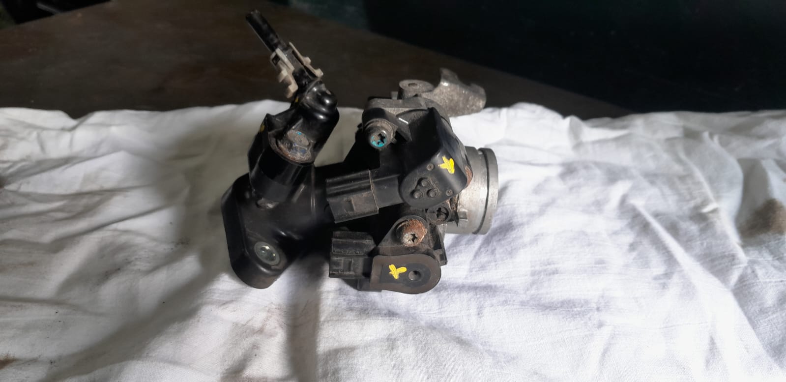
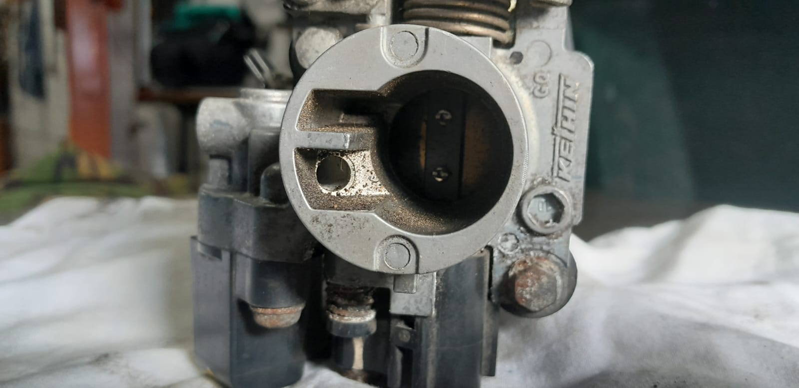
Picture 1: Throttle body
Picture 2: 2 pin fuel injector
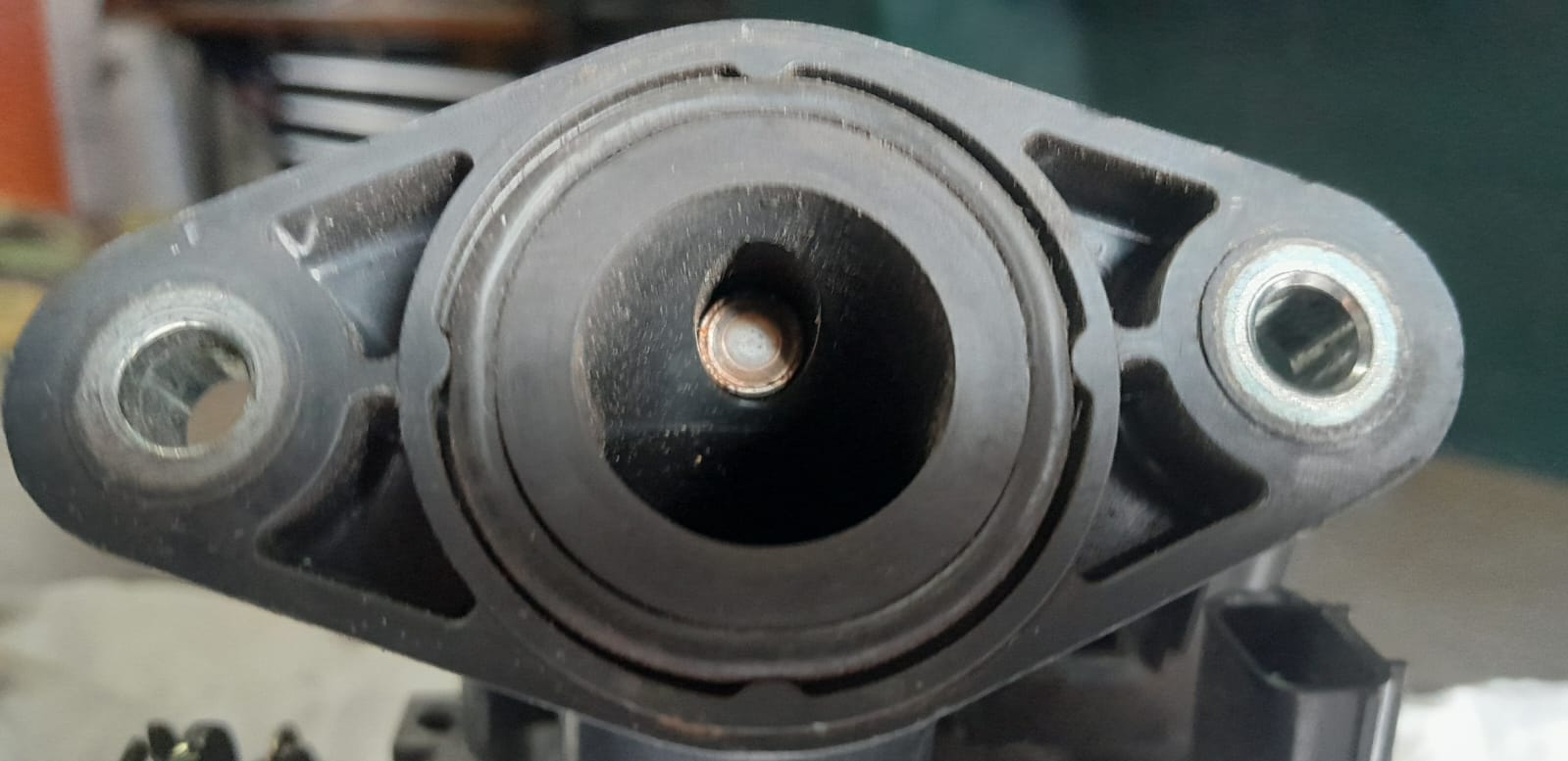
Picture 3: Fuel injector nozzle
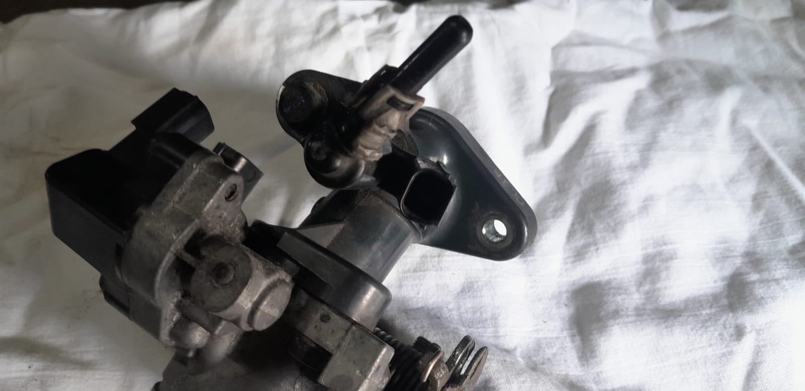
Picture 4: Throttle butterfly and air correct port(s)
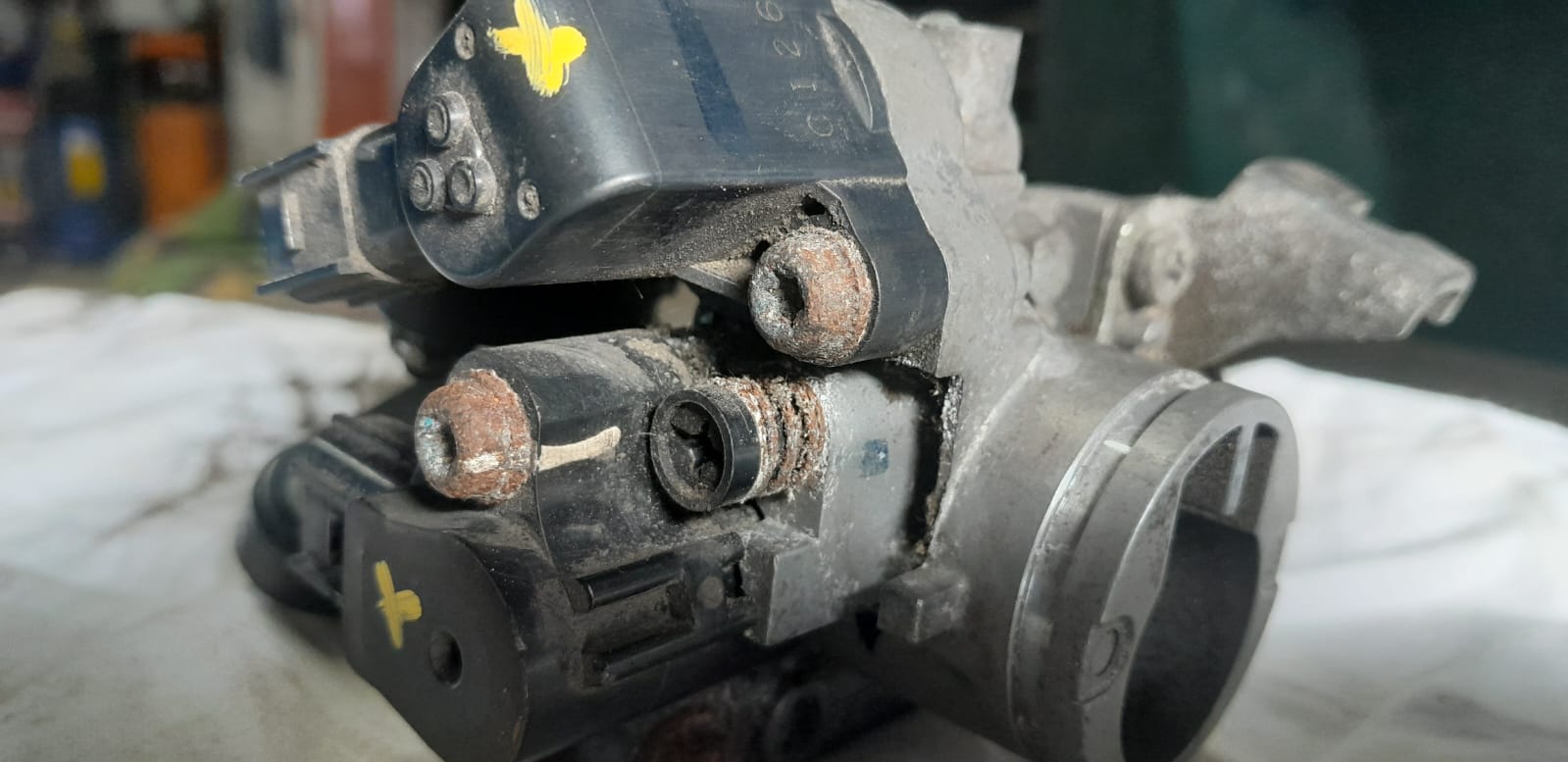
Picture 5: Upper air correct solenoid - lower throttle position/temp sensor - air correct screw
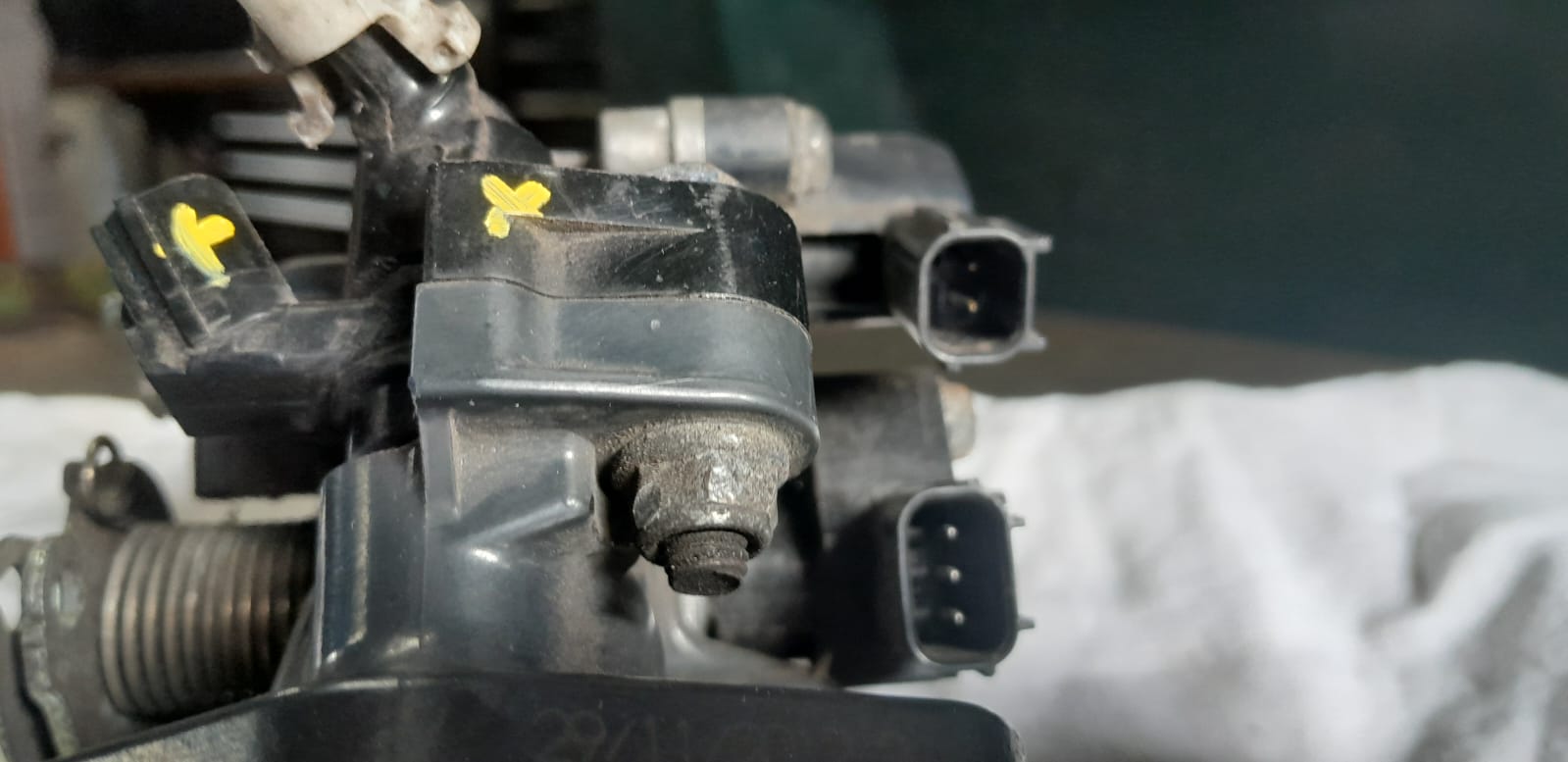
Picture 6: 2 pin upper air correct solenoid - 3 pin lower throttle position/temp sensor
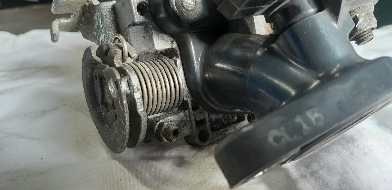
Picture 7: Manual throttle radius stop adjustment
Notes about pictures:
Picture 1: Throttle body. While the Wave 110i is described as being fuel injected - it is a simple set up - no closed loop fueling control - no oxygen sensor (O2) or manifold absolute pressure (MAP) sensor. Think more "electric carburetor" with idle air control - than fuel injection with closed loop fueling control.
Picture 2: Injector. Simple two pin coil over magnet injector - which requires 42psi from the in tank fuel pump - fed thru a screen bag fitler fitted to the intake of pump inside the fuel tank. The pump either runs or it don't - it primes when you turn key on - and you can test its delivery pressure with an 8mm bore hose connected to a fuel pressure tester gauge.
Picture 3: Injector nozzle. When removed from intake manifold - this should atomise not drip - with fuel connected and two pin plug connected and engine cranked you can test this. You can electrically test supply voltage to it and resistance across internal coil connection pins with a multimeter. But removal and cranking checks all three at once. It should be noted - with scope or HZ meter - there is no pulse width modulation when engine is cold reducing when hot. The injector delivers the same amount of fuel whatever the engine temp - just pulses more often as engine speed increases (no closed loop fueling control).
Picture 4: Throttle butterfly and air correct port. Throttle butterfly is controlled by the throttle cable. Air bleed port flow is controlled by static manual air correct screw and two pin idle air correct solenoid valve.
Picture 5: Upper air correct solenoid - lower throttle position/temp sensor - air correct screw. Upper air correct solenoid is what makes the engine RPM increase at lower temps. Lower throttle position sensor tells the ECU where throttle cable position/intake butterfly is. Temp sensor in lower sensor pack tells ECU what the intake temperture is. Air correct screw made of plastic - with a 2pt JIS head - controls low speed/idle fueling mixture - screw in clockwise to richen mixture - screw out anti clockwise to weaken mixture. Any adjustments to air correct screw should be made when engine is up to working temp. So to prove closed loop function of idle air control valve (cold start running) - spray cold solvent based aerosol brake cleaner at lower temp sensor and engine speed should increase. It must be noted: That any physical air leak around the throttle body or any failed O ring seal will cause running and idling problems.
Picture 6: 2 pin upper air correct solenoid - 3 pin lower throttle position/temp sensor. Two pin upper air correct solenoid can be tested electrically with a mutimeter for resistance across the internal coil or fired with power probe to test plunger operation. Supply voltage to it can only be tested if lower three pin sensor has had it's temp dropped (closed loop control). Lower three pin sensor pack can be tested with a multimeter for resistance - ohms should range up and down smoothly when throttle radius is moved thru its range smoothly. Temp sensor range should move in line with hot or cold being applied to sensor pack.
Picture 7: To adjust throttle radius stop - basic idle speed - you will need 7mm spanner and 2.5mm allen key.
I hope this explains what everything is - what it does and how to test it - simply and quickly with no wiring diagrams or manufacturers data........?
Part Numbers:
Throttle body: 16400K03H11
Injector: 16450K03H11
Injector base seal (O ring): 16472KPCD50
Plastic air correct screw with spring and O ring: 16016K03H11
Page updated 08-06-25